Centralized power generation technology is undergoing a revolution. Traditional power plants (such as coal-fired, gas, and nuclear power plants) are gradually being replaced by renewable and decentralized solutions (such as wind, solar, or biomass power plants). The latter type of power plant usually follows the same principle, which is to use renewable energy (solar energy, wind power, and biomass) and generate DC or AC voltage or current through one or more transformation processes. Due to the dispersed nature of energy producers, more and more electricity is no longer fed into high-voltage power systems, but into medium and low-voltage power systems. Therefore, in the future, there will be an increasing need for intelligent power system management using energy storage devices to meet peak load demands in a diverse manner. The core components of these power plants are power converters that can provide the generated electricity to the power system or consumers in a synchronous manner and with appropriate quality. These power plants not only impose extreme requirements on various components, but they must also achieve a lifespan of about 20 years under harsh environmental conditions.
In recent years, the development focus of power converters has shifted towards higher power density and higher switching frequencies of semiconductors. The first development makes it possible to improve cost-effectiveness, as it can increase output power while maintaining almost constant system costs. The second development increases system efficiency, as system losses decrease with an increase in switching frequency.
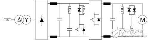
Conceptual circuit diagram of power converter
The power converter moves from the input side (left) to the consumer side (right) in the circuit diagram, with a resistor (RI) used to limit the charging current and protect the capacitor from interference. After being powered on, the resistor must accept a large amount of pulse energy. This energy flow or application occurs in a short period of time during capacitive charging and typically only needs to occur once (during start-up and without periodicity). This places special requirements on the resistance technology used. The adiabatic boundary condition exists due to the short duration of the pulse. Therefore, this energy is only applied to the effective material of the resistor (acTIve material), and will not propagate through thermal conduction throughout the entire resistor.
Compared with thick film or thin film technology, the winding resistance has a large effective mass and can therefore adapt to high pulse energy and continuous power. But low-power converters use all resistance technologies. This includes SMD-MELF thin film resistors, LTO thick film resistors, and the aforementioned winding resistors. If the power is high, series or parallel wound resistors can be combined into printed circuit board (PCB) components (G200, AC, RS, CW, FS, and Z300). When the power exceeds 50 W, there are many special winding resistors (such as GWK, GWS, CSxx, FST, FSE, EDGx, RSO, and GBS series) or thick film resistors (such as LPS or RPS on the heat sink, which can be installed away from the PCB due to the extremely diverse connection options) available for use.
After the AC voltage is converted to a suitable voltage level, the B6 bridge is used to adjust the AC voltage, and then an inductor is used to suppress interference. On the one hand, the series connection between the DC link resistor (RDC) and the DC link capacitor is used to limit the charging current of the DC link capacitor. This current generates relatively high but infrequent pulse loads. On the other hand, this series connection is used to suppress harmonics in the DC link circuit, which are equivalent to a continuous load (due to continuously repeating pulse sequences). Therefore, it is necessary to limit the resistance used to withstand continuous power and pulse power.
The latest power converters have the option of providing capacitive or inductive reactive power to power systems or consumers. This is achieved by increasing or decreasing the voltage of the DC link circuit. This increase is achieved using an internal boost converter or directly at the input position of the power converter. Chopping resistor (RBR) is used to reduce the voltage of DC link circuits by converting excess electrical energy into thermal energy. Power MOSFETs, IGBT modules, or thyristors provide resistance switching functions.
The power MOSFET and IGBT modules can perform high-frequency switching operations, but the thyristor only supports low-frequency operation. When there is a danger of the DC link circuit voltage exceeding the specified maximum value, these power switches will be connected to a chopper resistor. After the voltage of the DC link circuit drops due to this operation, the chopper resistor will be disconnected again. These chopper resistors are easy to install and have numerous connection options, with power dissipation ranging from 100 W to 1000 W. In this case, a combination of chopping resistor and crowbar resistor is often found. When downstream components fail, this combination makes it possible to completely dissipate the energy of the DC link into the resistor (RBR), thereby preventing damage to the power converter. Here, you can choose steel grids or steel plate resistors with the main component being steel. For these resistance types, extremely diverse alloy steel plates have ripple structures, and by cascading them, resistance values, continuous power, pulse power, and maximum surface temperature can be set as needed. The insulation between steel plates can be made of ceramic or mica materials. In addition, these steel plate resistors also have very low inductance, so no additional voltage spikes are generated during switching.
Steel grid resistors (such as Vishay GREx) are suitable for high continuous power due to their large surface providing natural convection cooling or the use of fans. The maximum achievable heat dissipation in this case is only limited by the available installation space and fan output. But if higher power is required and the insulation space is smaller, water-cooled resistors, such as the Vishay WCR series, can be used.
In addition to the limitations of transient input surge current, filtering, and the matching of the described DC link circuit, the DC voltage is also transformed into an AC voltage with variable frequency and pulse width through the H-bridge circuit shown. The filter resistor (RHF) and series output capacitor are used to suppress harmonics on the output stage. In addition, RHF also has the function of limiting the charging current of the filtering capacitor. Wirewound resistors with end caps (such as the GWK and FVT series) are suitable for filtering applications due to their convenient installation and high pulse power and continuous power. The difference between this series of products is that their stable glass insulation has moisture resistance and chemical cleaning material resistance. The GWK and FVT series can also easily achieve low inductance and resistance. In this regard, there are two resistance wires wrapped in a double stranded manner.